
Since my last update, I’ve been concentrating on completing the first hardware iteration of my robot. Previously, the robot existed as a basic prototype, and it required significant improvements. This post aims to provide a brief summary of the progress made and the tasks accomplished.
Motors and gears
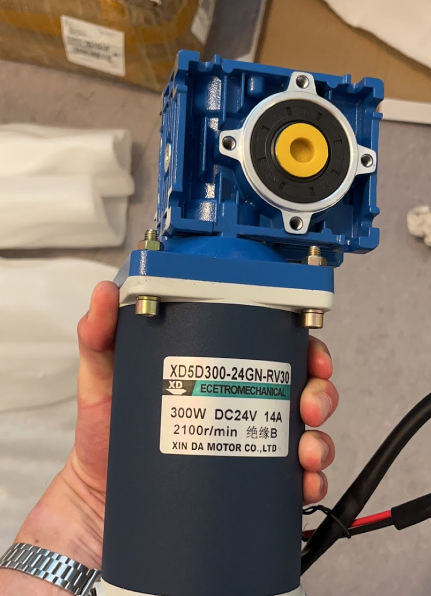
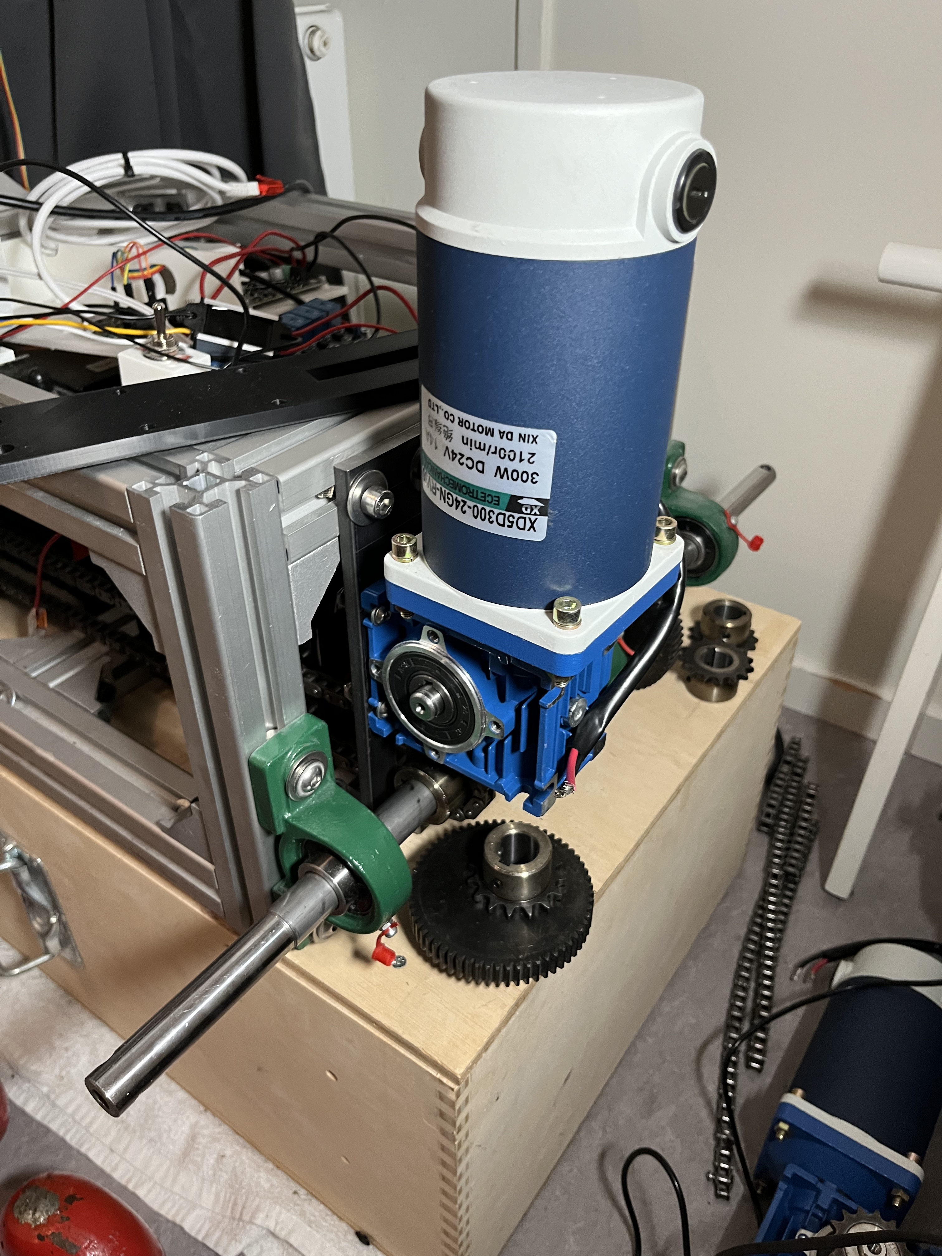
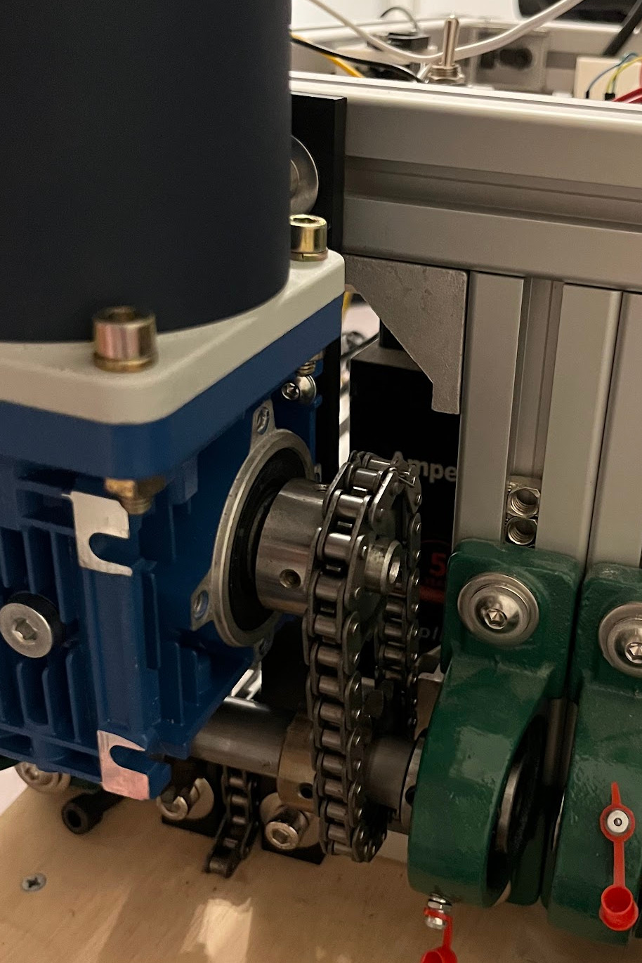
I was a bit surprised when the two 200-Watt motors with a worm gear gearbox I had ordered turned out to be 300-watt. The supplier had sent me the wrong ones, but I’m not complaining. Additionally, I received new gears and a chain, and I used them to fix the connections between each side and their respective front and back wheel axles.
The image below illustrates how the worm gear gearbox functions. Essentially, the top screw part rotates, causing the large gear to turn. The reason I chose this solution is because it can only turn in one direction. The motor turns the screw, which in turn rotates the big gear. It can’t turn in the opposite direction, effectively acting as a passive brake when the motors are turned off. The first prototype had a problem with this and if you want to read more about it you can click here.
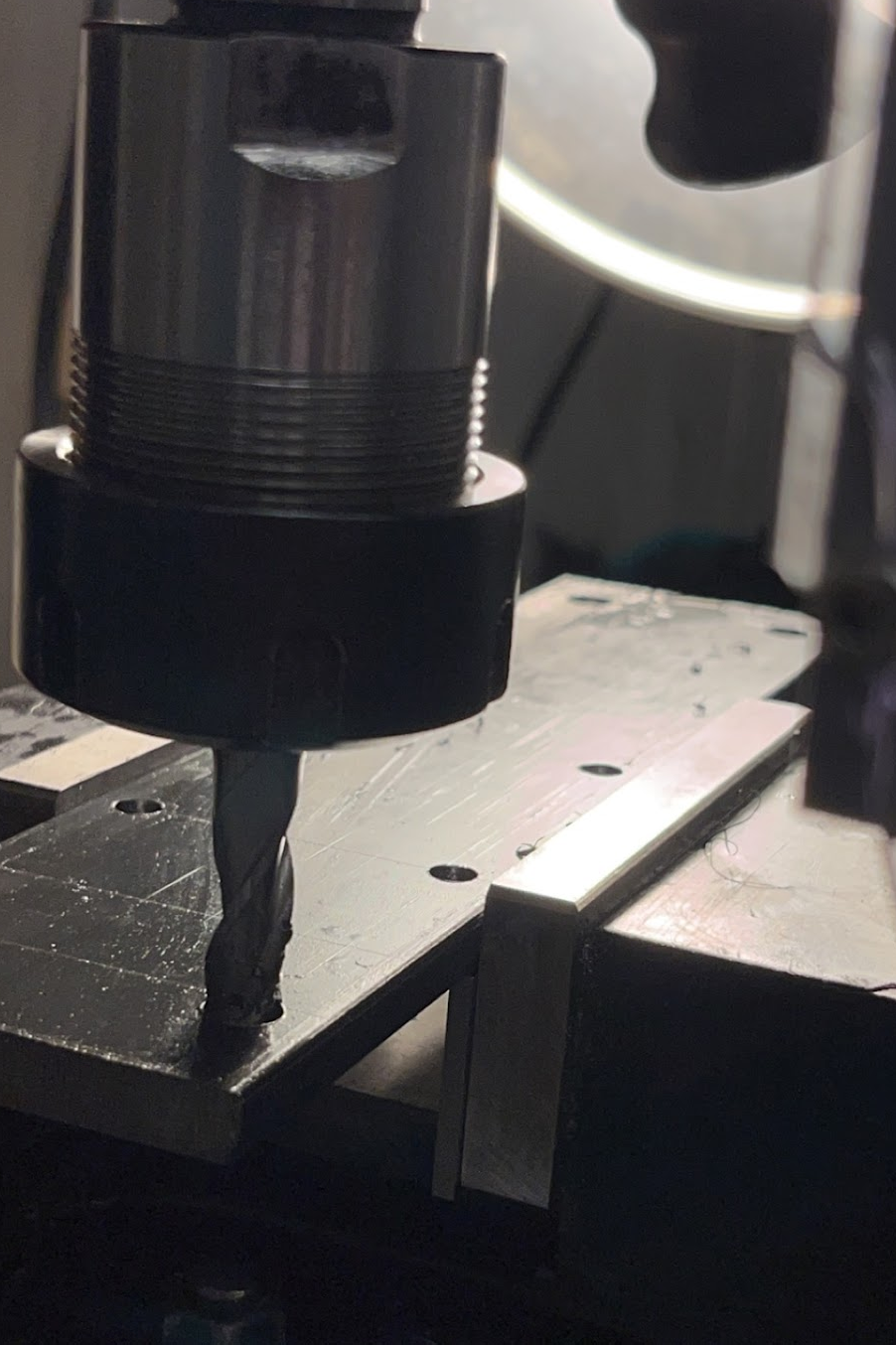
I fabricated mounts for each motor at the back using a vertical mill. Additionally, I successfully connected each motors their wheel axles.
Electrical stuff
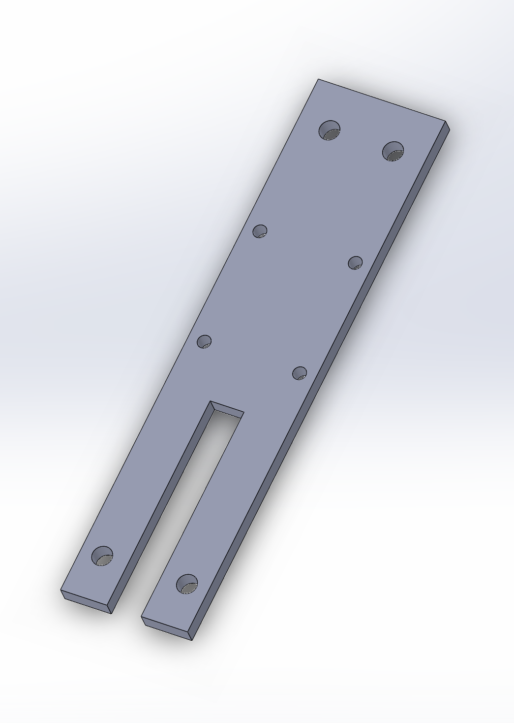
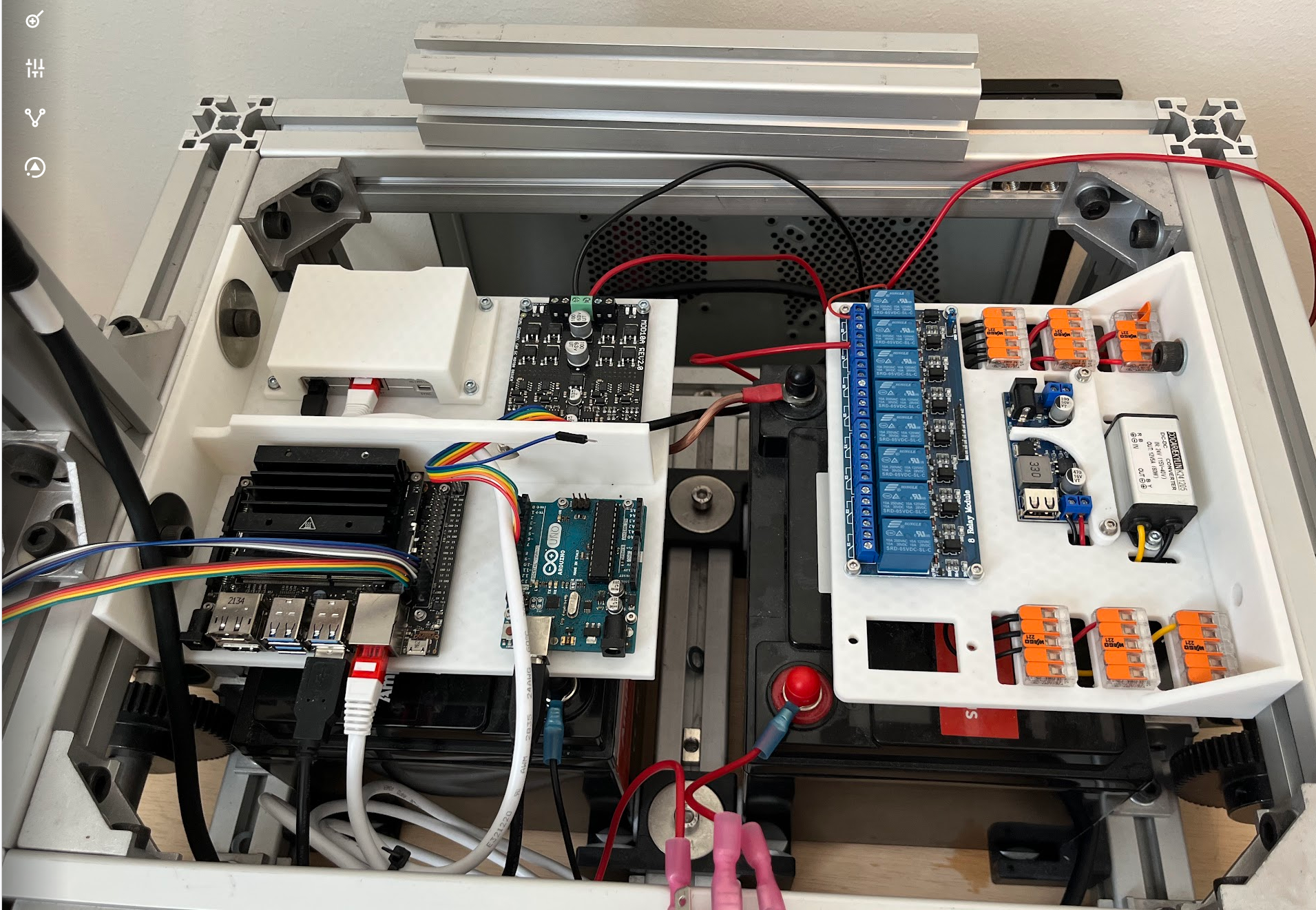
I designed two mounting boards to segregate the computing units and the connecting units. On the left board, the top left corner accommodates my Livox driver, connected to the LiDAR. Adjacent to it is the motor driver responsible for controlling the motors. Positioned at the bottom left is my Jetson Nano, serving as the main computer on the robot. Next to it, there’s an Arduino responsible for sending PWM signals to the motor driver.
On the right board, there are two DC-DC converters (24-12 volt and 24-5 volt). There are two orange connectors, each with five slots for 24 volts, along with individual connectors for 12 and 5 volts. The board with the blue boxes hosts an 8-relay module, enabling me to manage power to various units such as the LiDAR, fans, etc, by toggling the relays.
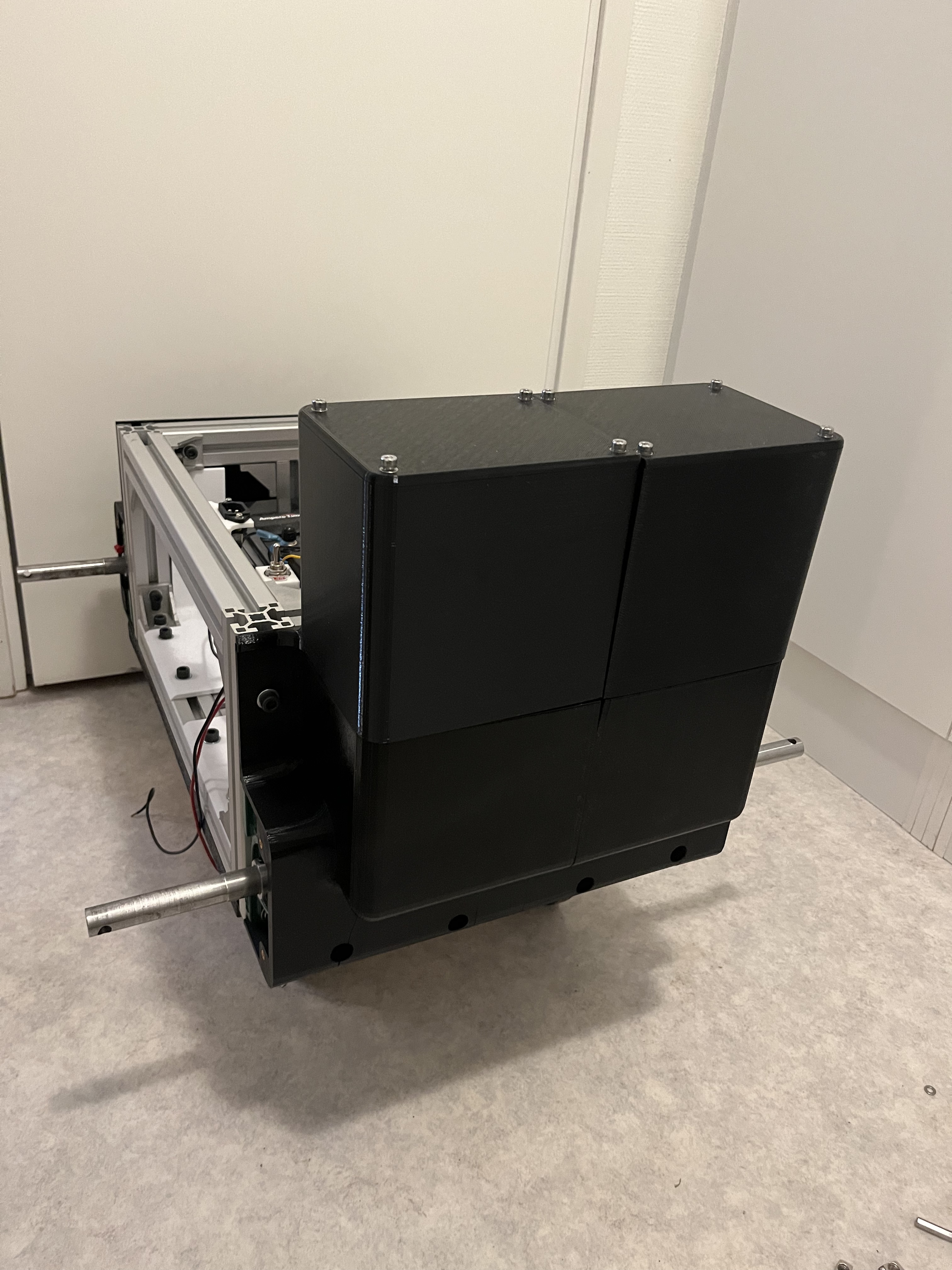
Chassi
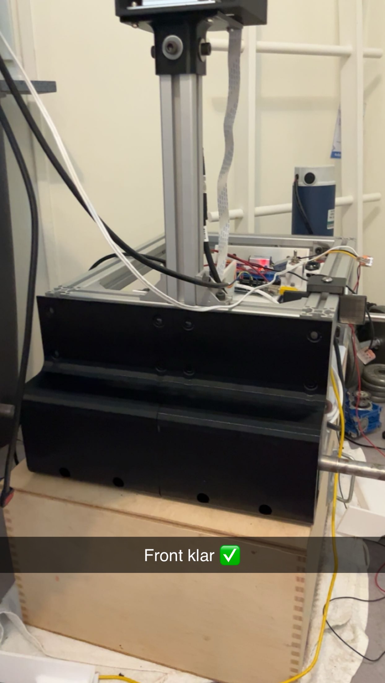
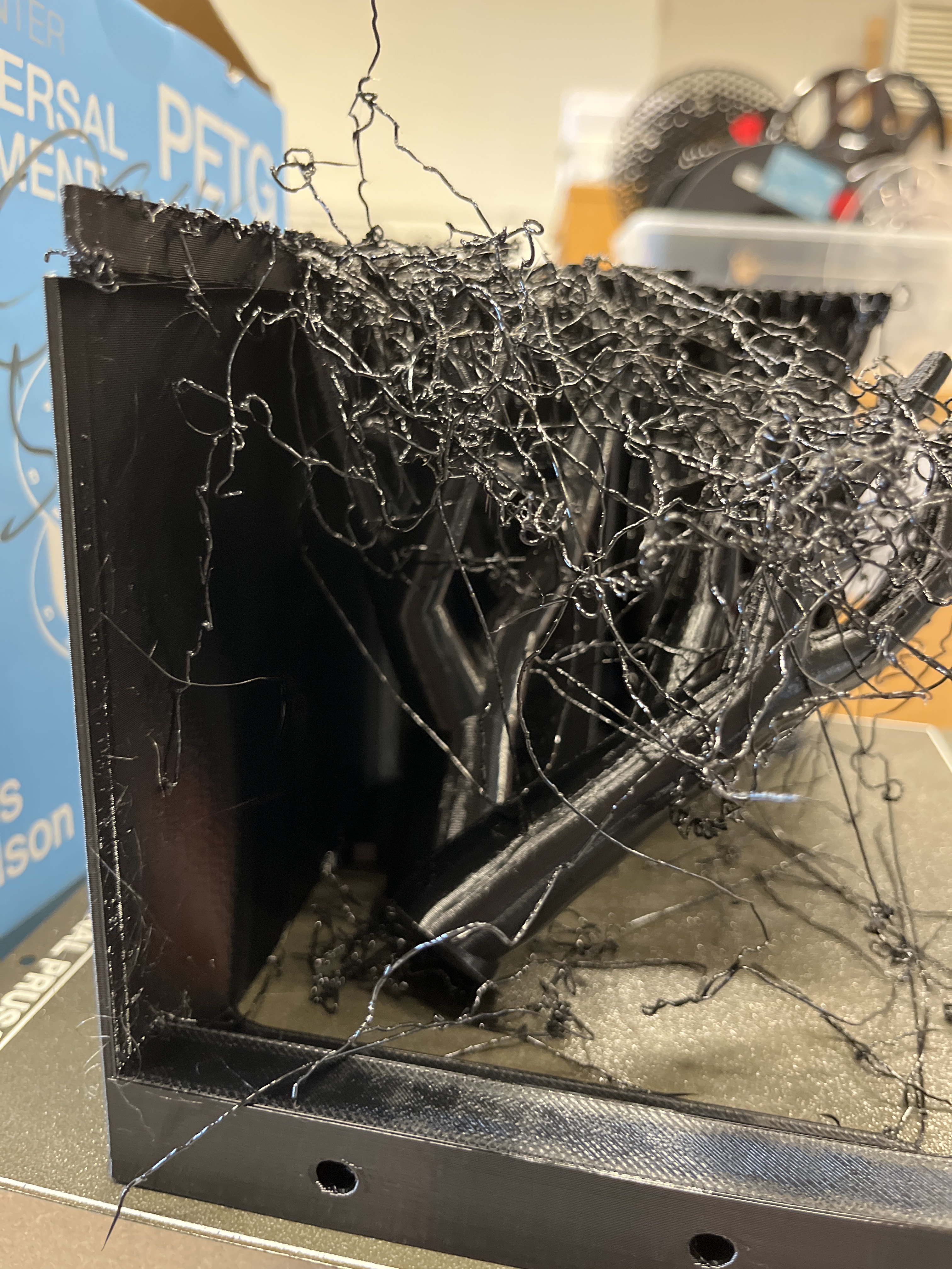
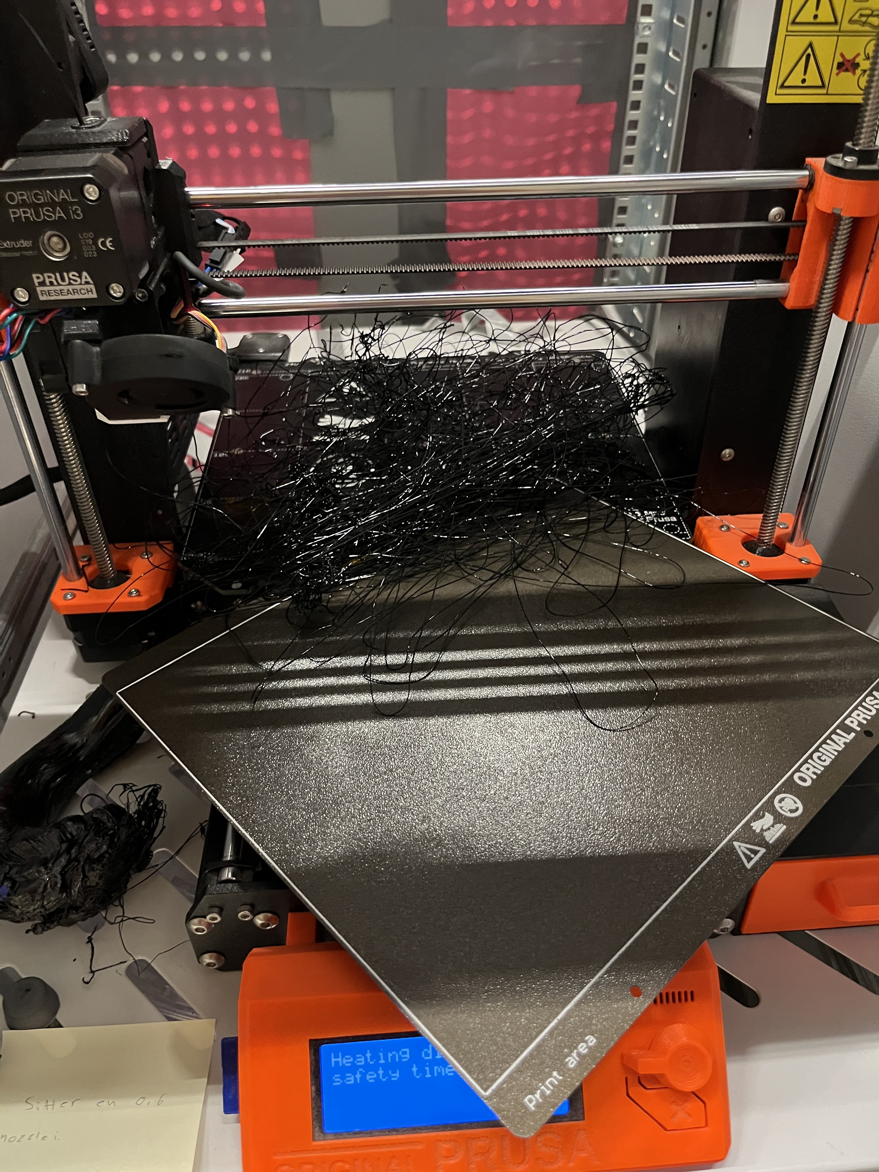
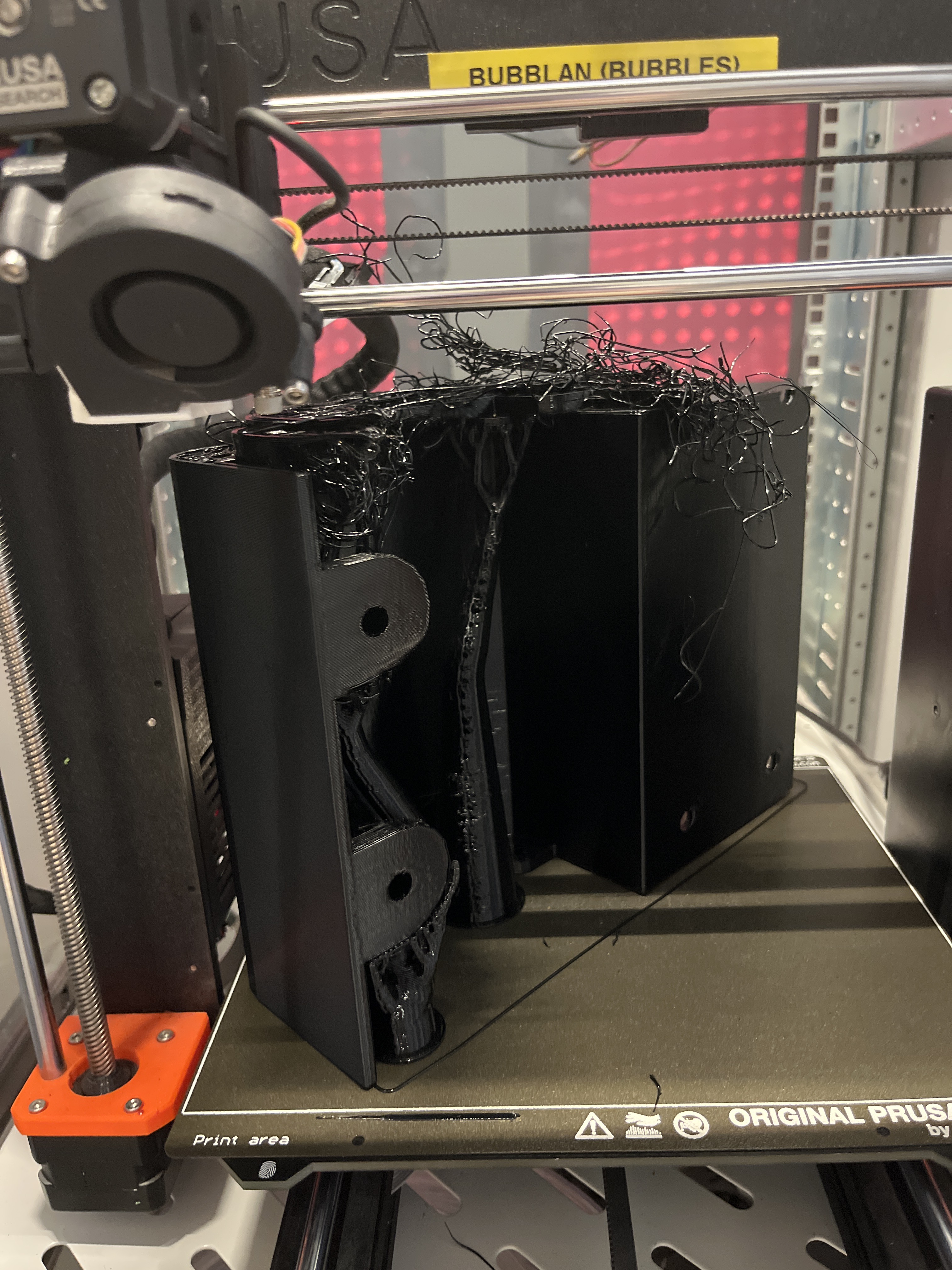
I created and 3D printed both the front and back panels. Additionally, I acquired metal sheets for the bottom, sides, and top sections, which I painted. However, printing large parts posed some challenges, resulting in several failed attempts before achieving success.
Test run
I conducted my initial test run by controlling it with a game controller. It was quite enjoyable watching it drive.
Project update
I enjoy designing hardware, although it can be time-consuming. When a part fails or doesn’t function as expected, it often results in a lengthy delay before another attempt can be made. As this hardware development phase nears completion, I’m looking forward to transitioning into a more software-intensive period. I recently acquired a new IMU that will enable me to begin working on 3D mapping in combination with the LiDAR
